QAC Automotive and Robotics (QAaR) Quality Assurance
FOCUSED ON THE FUTURE
Welcome to the sixth edition of the QAaR newsletter. In this edition, we’ll focus on sharing more information about vehicle data and different types of communication networks that might be part of a vehicle. This document will go into more detail about the most important communication protocol in CAV vehicles, CAN, and how the data generated by several components can be used for testing purposes.
Keeping you informed
Our automotive and robotics quality assurance workstreams
Automotive System Integration Testing
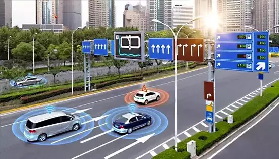
Mesh Model with Static and Dynamic Obstacles
Challenges to the test vehicles
- How to identify an action and the components involved?
- What components are impacted by an action?
- What component(s) is (are) expected to receive data messages?
- What is the communication protocol (network + data type)?
- How do we capture the information we can identify the in-vehicle network?
- How we ensure the expected components received specific communication from another component and reacted as expected?

SIT testing components in a vehicle can be complex. The picture above shows a small portion of components required to be checked during a simple test that goes through several different communication protocols. Through a model-based testing approach, we have built out all valid SIT test cases based on the components and how they interact with each other. Each component may respond in a different way given an action performed by the driver, the passenger or by another component in the vehicle.
Example of Automotive Components and Some of their States
System
- Control Timing
- Idle Speed
- A/F Mixture
Speed Control Units
- Cruise
- Adaptive Cruise
- Manual
Gear
- Parking
- Reverse
- Neutral
- Drive
System
- Pos1 Open
- Pos2 Close
- Pos3 Partial
System
- Send warning
- No warning
Lane Keep
- Correct right
- Correct left
- No correct
Lane Centering
- Continuous correction
- Disabled
System
- Radio (AM/FM)
- CD/DVD
- Aux 3.5mm
- USB
- Bluetooth
Voice Commands
- Text
- Phone
System
- On
- High
- Off
Brake Lights
- On
- Off
Turn Left Front Light
- On
- Off
Turn Left Rear Light
- On
- Off
System
- Low
- Med
- High
Head Direction
- Foot
- Foot & Body
- Body & Face
- Windscreen
Defrost Rear
- On
- Off
Cluster
- Zero
- Low
- Med
- High
Low Fuel
- Alert off
- Alert on
Washer Fluid
- Alert off
- Alert on
The idea behind how automotive system integration tests happen
A model that abstracts a vehicle can be represented by a set of components and how their states interact with other components and their respective states. When a state of a component changes from an initial state to a different state, that change might affect one or more components in a vehicle. If we consider a simple scenario where two vehicle’s components are verified: Gear, an engine system component; and Speedometer, an instrument cluster component, whenever a gear state changes to reverse (either from parking to reverse, or from neutral to reverse), the speedometer is affected and should have its state set to zero.
In the test execution framework developed by our team, we call an activator any component which state affects one or more components in a vehicle. The impacted components, the ones that react to an activator is called a responder. The mechanism of checking the current state of a component is called the listener.
In order to understand how a listener works and all mechanisms involved in the process of listening, we need to understand how the states of a component can be identified. Although the high complexity of the whole framework, the idea is relatively simple: components in a vehicle keep communicating each other all the time, sending and receiving messages through different buses, known as communication networks and further detailed in next sections.
Vehicle Communication Networks
- Controller Area Network (CAN)
- Media Oriented Systems Transport (MOST)
- Local Interconnect Network (LIN)
- Flexray Automotive Communication Bus
- Automotive Ethernet
- Onboard Automotive LTE, Wi-Fi, and Bluetooth connected devices

CAN protocol is the current standard for a vehicle communication network, used for several purposes, including powertrain, chassis, and body systems. MOST is a bus standard for vehicle multimedia networks designed to enable the transfer of high-quality audio, video, and data. LIN is a vehicle communication protocol that uses a single master to achieve a superior cost-performance ratio, used in switch input and sensor input actuator control. FlexRay is a high-speed communication protocol that provides a high degree of flexibility and reliability. Automotive Ethernet is basically a diagnostic protocol for engine, chassis, and body electronic connection control units used for network connections.
As an example, ECU controls items such as crank position and air-fuel mixture which will maximize thrust while conserving fuel. As you accelerate, the engine control unit will tell the combustion components to speed up hence the car will go faster. When an ECU or component fails, it will produce a fault code which can be read through the On-Board Diagnostic (ODB). This mechanism is ideal not only for testing but for diagnostics on vehicles after purchase. As our automotive system integration testing model evolves, our technology advances to understand all those communication protocols and improve the listeners’ capabilities to detect the current state and. From there, the test execution can be performed by the framework to validate that the state matches the expected results from a test case.
QAC Investing on Quality Assurance Technologies for Automotive Industry

Our approach focuses on a model-based SIT framework that constitutes four main steps: generation of the system’s functional model, generation of test cases, prioritization of test cases, and execution of test cases using a machine learning algorithm. The system under test (SUT) model comprises both physical hardware-in-the-loop (HIL) and virtual (simulated) components.
STAY TUNED
Our partners: